|
|
||||||||
| how
TRIAC dimmer circuits work
TRIACs
are like 2 parallel SCRs Through the use of optical coupling they can be safely interfaced with computer control circuits!
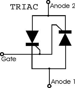
TRIACS are like 2 parallel SCRs and can handle both sides of a sine wave.
Here is the internal semiconductor structure of a TRIAC
A pushbutton switch controls the flow of current in a load
Current injected into the GATE controls the TRIAC
A TRIAC switch
controls the current through a load
The TRIAC is a gate controlled switch.
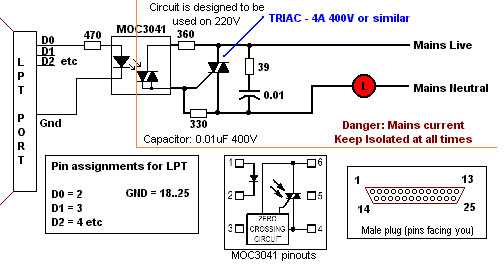
Low voltage logic circuits are fragile and expensive they should be electrically isolated from the high voltage TRIAC circuit using an Optocoupler module chip
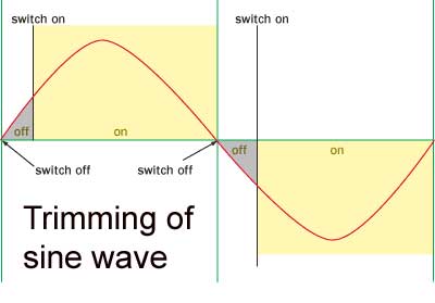
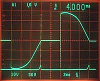
RMS power and voltage to the load are controlled by trimming of the AC sine wave.
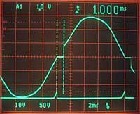
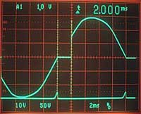
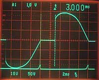
An oscilloscope connected to a TRIAC controlled load shows the progressive trimming of the SINE wave that effectively controls the RMS power to the load.
The variable resistor sets the point on the
sine wave where trimming occurs effectively dimming or illuminating the
light.
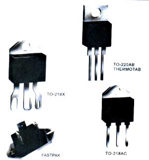
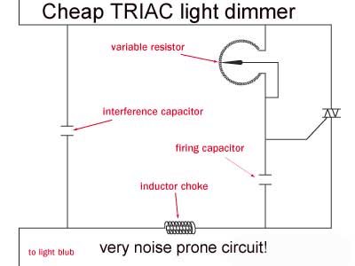
Typical home
light dimmer uses a TRIAC
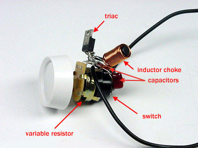
Here is the actual view of the
circuit above.
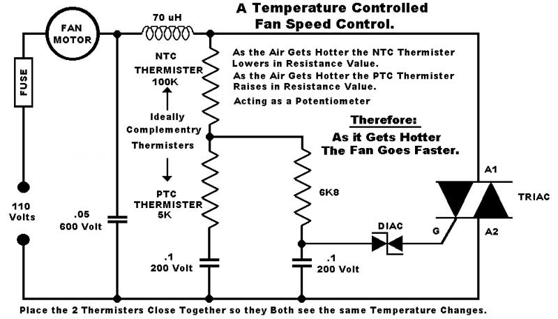
The fan is trying to keep the environment cool
(CPU, industrial process,
engine)
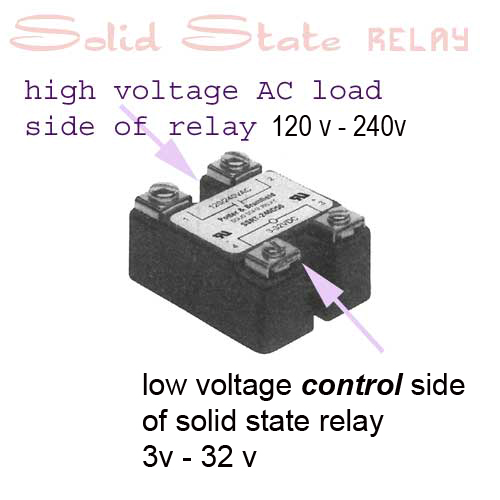
Here a low voltage
logic circuit is used to control a higher voltage AC load
(heater motor).
One side of this The other side is for
high voltage AC load control
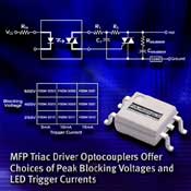
Here is typical TRIAC driver package used to interface low logic control circuits to controlled high voltage AC loads.\ The Optocoupler circuit and TRIAC are contained in the same package.
Actual module for TRIAC load control using the Fairchild MOC3062 6-Pin DIP 600V Zero Crossing TRIAC Driver Output Optocoupler
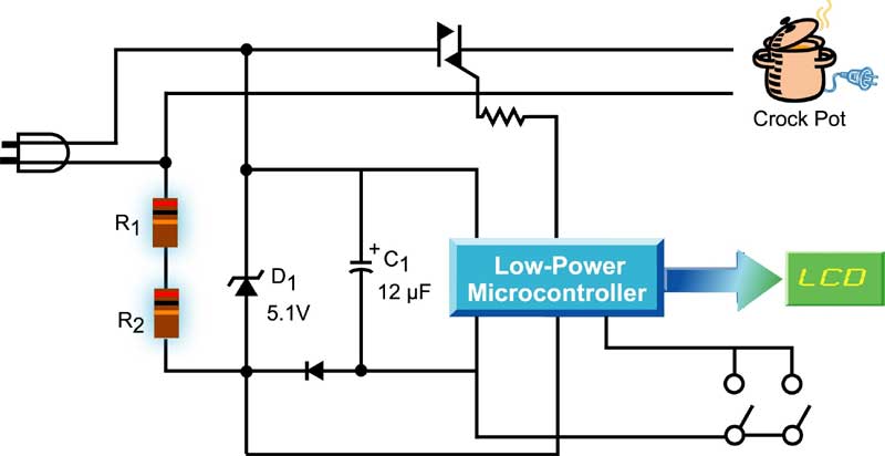
A programmable TRIAC crock-pot controller.
Fairchild MOC3041 Optocoupler interfacing a computer and AC load |
|||||||||
|
|
|||||||||